This chapter shows you how to write text and draw graphics on the live video images.
The source code for this sample program can be found in the samples\VB6\Creating an Overlay directory.
First of all, create a new project and add IC Imaging Control to the form as shown in the FirstSteps chapter.
Then, insert three new buttons to your form and name them cmdSelectDevice, cmdLiveVideo and cmdImageSetting. Label the buttons Device, Start and Settings respectively. These buttons will be used to select the video capture device, start and stop the live video and open the image settings dialog.
Now, implement the handler subs for the three buttons:
Also, implement a sub named StartLiveVideo. It is called by cmdLiveVideo_Click and will be used later to do the initial drawings in the overlay.
Run the program: You should be able to select a video capture device and see the live video.
IC Imaging Control provides a special object for drawing and writing on the live video. The object is called OverlayBitmap.
The OverlayBitmap object contains a bitmap, which has the same size as the video format, or the size of a frame filter that transforms the image data before the overlay bitmap is applied. An application can draw text and graphics on this overlay bitmap. The overlay bitmap is copied to each sample of the video. A dropout color can be specified to determine, which pixels of the overlay bitmap are transparent and therefore not copied to the live video.
The overlay bitmap can only be used, if ICImagingControl.LiveStart has been called at least once after the video format has been changed. It is only visible, if the live video is running.
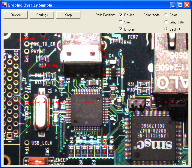
Since version 3.0, IC Imaging Control allows you to select whether the overlay is drawn on live video, on grabbed and recorded images, or both.
You can use ICImagingControl.OverlayBitmapPosition to set an ORed combination of PathPositions values that specify the path positions at which overlay bitmap objects are inserted.
Enabling the overlay bitmap is a two-step process: The OverlayBitmapPosition has to be set before starting live mode and determines, at which path positions overlay operations are possible. OverlayBitmap.Enable enables or disables the application of a specific overlay bitmap while live mode is running.
To access one of the 3 OverlayBitmap objects, use ICImagingControl.OverlayBitmapAtPath. The parameter of that property selects the position of the OverlayBitmap that is accessed.
The ICImagingControl.OverlayBitmap property returns the OverlayBitmap for the device path.
A program can draw on any of the overlay bitmaps once live mode has been started. Live mode has to be started first, because the actual size and color format of the overlay bitmaps can depend on frame filters, thus it is impossible to determine the formats before.
The StartLiveVideo starts live video and then draws several graphics on the 3 overlay bitmaps:
The SetupOverlay sub is used to initialize each of the 3 overlays. It is called after live mode has been started.
The overlay is enabled by calling OverlayBitmap.Enable, and a text is displayed in the upper left hand corner of the bitmap. The sub also sets a dropout color.
The OverlayBitmap.DropOutColor property of the OverlayBitmap object determines, which pixel color is transparent on the live video. Each pixel that has the dropout color is not copied to the live video. The dropout color can be set with Visual Basic's RGB function. It defaults to black. For this reason, the background of the text written above is transparent. The FontBackColor property of the OverlayBitmap object is set to black as default too.
In order to be able to use black color in the overlay, we change OverlayBitmap.DropOutColor to another color, for example magenta (RGB(255,0,255)). If the application is started, only a black image with our text can be seen. The image is black, because the overlay bitmap is black and the dropout color has been changed to magenta. Therefore, the overlay bitmap must be filled with magenta. The method OverlayBitmap.Fill does this for us. When the dropout color is changed, the text background is visible as a solid black rectangle. To hide this, the property OverlayBitmap.FontTransparent can be set to True.
In the next step, we are going to draw a coordinate plane, consisting of lines and labels. To do this, we are going to use the DrawLine and DrawText methods of the OverlayBitmap object. Additionally, we are going to change the font used to write the labels.
We are going to implement a new sub called DrawCoordinatesystem. We want to use an 8 dpi Arial font for the labels. To achieve this, a new StdFont object Font must be created. This object has font properties like font name, font size and other font attributes. Before changing the font, we save the current font in order to be able to restore it after we have completed the coordinate plane.
The Font property of the OverlayBitmap object receives the StdFont object. Now, the new font is used for all following OverlayBitmap.DrawText calls.
The complete sub that draws the coordinate plane is implemented as follows:
To display the current time on the live video, a timer is inserted in the form. It is called timer1 by default and its timer interval is set to 1000 milliseconds in the property window. The timer event handler sub is called Timer1_timer. The current time is displayed in the lower right hand corner. It has a white font with a black background. Furthermore, it has its own font. Therefore, a StdFont object must be created and used, as described above. The property OverlayBitmap.FontTransparent is set to False and OverlayBitmap.FontBackColor is set to black (RGB 0 0 0).
IC Imaging Control provides an OverlayUpdate event. This event is called after a new frame has been delivered from the video capture device. Therefore, it is possible to insert individual information on to each frame (i.e. frame counter).
The OverlayUpdate sub in the example counts the frames in the variable FrameCount. The frame counter is used to draw a growing triangle. If the frame counter is greater than 25, it is reset to 0 and the triangle is deleted. Therefore, if a solid rectangle of the same size is drawn over the triangle. The color of the rectangle must be set to the DropOutColor to make it transparent. The method DrawSolidRect provides this functionality.
The OverlayUpdate event handler is implemented as follows:
The OverlayBitmap object does not provide all functionality of the graphic device interface (GDI). Therefore, the OverlayBitmap provides a method that returns a device context. The method is called GetDC. The bitmap of the OverlayBitmap object is already selected in the returned device context. It can be used for all GDI functions like BitBlt, Ellipse etc.
To use the GDI functions, they must be declared on top of the form's source code:
A new sub ShowBitmap is implemented to demonstrate how to render a bitmap onto the overlay bitmap. It uses the GDI function BitBlt to copy one bitmap onto another. The sub contains a variable of Visual Basic's StdPicture type. It is used to load a bitmap from file. Also two long variables are declared, that receive the device contexts. BitBlt copies the bitmap data from one device context to another device context. Very important: The bitmap sizes of the StdPicture object must be converted in to pixels, because the overlay bitmap uses pixels as its units.
After the bitmap has been loaded and its size has been converted to pixels, the device context of the OverlayBitmap object is retrieved:
Set ob = ICImagingControl1.OverlayBitmap
obDC = ob.GetDC
If an error occurs or GetDC is called before LiveStart has been called, 0 is returned. This means, the device context does not exist at this time. This has to be checked by an if statement.
Once a valid device context has been retrieved, a second, compatible device context must be created. This is done by a call to the GDI function CreateCompatibleDC. With the GDI function SelectObject, the bitmap in the StdPicture object is selected in the new device context. As soon as these steps have been completed, the BitBlt function is called. The target coordinates are so calculated that the loaded bitmap appears in the upper right hand corner of the video image.
Do not forget to delete the newly created device context by a call to the GDI function DeleteDC and to release the OverlayBitmap device context by a call to the method ReleaseDC of the OverlayBitmap object.
The end user of our example program can control which of the 3 overlay bitmaps are drawn on the live video. To change the PathPositions, the following helper sub is used:
This sub enables or disables the overlay at a specified path position.
An application can decide whether it wants a color or grayscale overlay. The OverlayBitmap.ColorMode property can be used to select one of the available color modes:
When the format of the image data stream does not match the overlay bitmap color mode, the image data is automatically converted.