3D-Sehen leicht gemacht
Veröffentlicht am 21. Juni 2017 von TIS Marketing.
3D Daten-Akquisition: Passive und Aktive Techniken
Sei es der smarte Industrieroboter im Industrie-4.0-Zeitalter, der sich durch dreidimensionale Informationen im Raum orientiert, der Leergutautomat, der die Flaschen im Getränkekasten zählt, oder Oberflächeninspektionssysteme, die kleinste Materialdefekte aufdecken - dreidimensionalen Informationen von Umgebung und Objekten, akquiriert durch moderne 3D-Sensorik, gehört in vielen industriellen Applikationen die Zukunft.
Mittlerweile existieren am Markt unterschiedliche Technologien, um dreidimensionale Informationen einer Szene zu akquirieren. Dabei muss grundlegend zwischen aktiven und passiven Verfahren unterschieden werden: Aktive Verfahren, wie zum Beispiel "Lidar" (Light detection and ranging) oder Time-of-Flight-Sensoren, setzen eine aktive Lichtquelle ein, um Entfernungsinformationen zu bestimmen; passive Verfahren nutzen lediglich die durch Kameras akquirierten Bildinformationen, ähnlich der Entfernungswahrnehmung des menschlichen visuellen Wahrnehmungssystems.
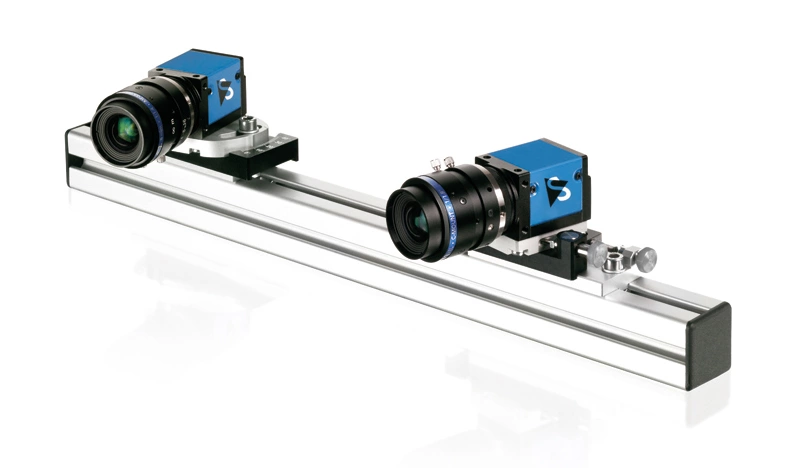
Alle Verfahren bringen jeweils Vor- und Nachteile mit sich: Während Time-of-Flight-Systeme in der Regel mit wenig Rechenaufwand auskommen und kaum Einschränkungen bezüglich der Szenenstruktur mit sich bringen, so ist die Ortsauflösung aktueller Time-of-Flight-Systeme mit maximal 800x600 Bildpunkten eher gering und ihr Einsatz in Außengebieten durch die Infrarotstrahlung der Sonne stark eingeschränkt. Passive (Multi-View-) Stereosysteme bieten aufgrund der mittlerweile verfügbaren Bildsensoren sehr hohe Ortsauflösungen, erfordern aber einen nicht zu unterschätzenden Rechenaufwand und leiden unter schwach oder sich stark wiederholend texturierten Szenen. Nichtsdestotrotz ermöglichen heutige Rechen-Ressourcen sowie optionale Musterprojektoren den Echtzeit-Einsatz von Stereosystemen bei hohen Orts- und Tiefenauflösungen. Gerade deshalb zählen sie zu den beliebtesten und vielseitigsten Systemen für die Akquisition von 3D-Informationen. (Multi-View-) Stereosysteme bestehen aus zwei oder mehr Kameras, die gleichzeitig eine Szene akquirieren. Sind die Kameras kalibriert und lässt sich zu einem Objektpunkt in der Szene dessen Bildpunkt in den einzelnen Kamera-Ansichten wiederfinden, so lässt sich der dreidimensionale Objektpunkt aus den Bildpunkten durch Triangulation rekonstruieren. Dabei hängt die erreichbare Genauigkeit vom Abstand der Kameras zueinander (Baseline), dem Vergenz-Winkel zwischen den Kameras, der Pixelgröße des Sensors und der Brennweite ab. Die essentiellen Komponenten Kalibrierung und Korrespondenzfindung stellen dabei bereits hohe Ansprüche an die zugrundeliegenden Bildverarbeitungsalgorithmen.
Stereosysteme im Echtzeit-Einsatz
Durch die Kamera-Kalibrierung werden sowohl die Positionen und Orientierungen der einzelnen Kameras ermittelt ("externe Parameter") als auch die Brennweiten, Hauptpunkte und Verzerrungsparameter der Kameras ("interne Parameter"), die maßgeblich durch die eingesetzte Optik beeinflusst werden.
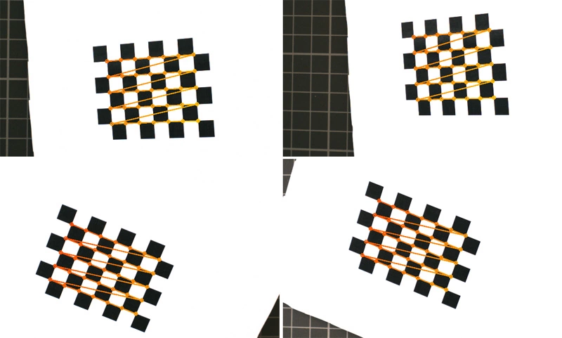
Die Kamera-Kalibrierung findet in der Regel durch zweidimensionale Kalibriermuster wie Schachbrett- oder Punktmuster statt, in denen sich markante Punkte möglichst leicht und eindeutig detektieren lassen. Dabei sind die Maße der Kalibriermuster wie zum Beispiel Abstände der markanten Punkte zueinander exakt bekannt. Von diesen Kalibriermustern werden nun zunächst Bildsequenzen mit variierenden Musterpositionen und Orientierungen akquiriert. Bildverarbeitungsalgorithmen detektieren die markanten Punkte des Kalibriermusters in den Einzelbildern. Als Basis dienen dabei zum Beispiel Ecken- und Kantendetektoren im Fall einfacher Schachbrettmuster oder aber Blob-Detektoren bei Punktmustern. Auf diese Weise ergibt sich eine Vielzahl an 3D-2D-Korrespondenzen zwischen Kalibrierobjekt und Einzelbildern. Auf Basis dieser Korrespondenzen liefert ein Optimierungsverfahren anschließend die Kameraparameter.
Während die Kalibrierung nur einmalig durchgeführt wird - unter der Voraussetzung, dass sich die Kameraparameter im Betrieb des Systems nicht mehr ändern -, muss die wesentlich rechenaufwendigere Korrespondenzfindung zwischen den Ansichten für jede Aufnahme durchgeführt werden, um die 3D-Informationen der Szene zu ermitteln. Im Falle eines Stereosystems werden dabei Korrespondenzen zwischen zwei Ansichten ermittelt. Als Vorverarbeitung findet in der Regel eine Entzerrung der Bilder anhand der kalibrierten internen Verzerrungsparameter statt. Für einen Bildpunkt in der Referenzansicht wird anschließend der korrespondierende Punkt in der Zielansicht gesucht, der den gleichen Objektpunkt abbildet. Das 'Lambertsche Beleuchtungsmodell' - also diffus reflektierende Oberflächen - vorausgesetzt, sollten sich lokale Umgebungen korrespondierender Bildpunkte in den Ansichten stark ähneln. Für ein gegebenes Ähnlichkeitsmaß - gängig ist zum Beispiel die normalisierte Kreuzkorrelation - werden Ähnlichkeitswerte einer lokalen Umgebung eines Punktes in der Referenzansicht und lokalen Umgebungen in der Zielansicht ermittelt.
Korrespondierende Punkte
Als Kandidaten in der Zielansicht kommen dabei nicht alle Punkte in Frage: Geometrisch liegen mögliche korrespondierende Punkte in den entzerrten Ansichten auf einer Geraden, der sogenannten Epipolar-Geraden. Nur entlang dieser Geraden muss also nach korrespondierenden Punkten gesucht werden. Um diese Suche weiter zu beschleunigen, findet häufig eine Rektifizierung der entzerrten Eingabebilder statt. Dabei werden die Eingabebilder so transformiert, dass für alle Punkte in der Referenzansicht die Punkte der Epipolar-Geraden die gleiche vertikale Koordinate wie der Referenzpunkt aufweisen. Für einen Punkt in der Referenzansicht ist also nur entlang der gleichen Bildzeile in der Zielansicht nach korrespondierenden Punkten zu suchen. Während die Komplexität der Suche gleich bleibt, ermöglicht die vorherige Rektifizierung eine effizientere Implementierung der Korrespondenzsuche. Sind ferner der minimale und der maximale Arbeitsabstand in der Szene bekannt, so kann die Suche entlang der Epipolar-Geraden weiter eingeschränkt und somit beschleunigt werden.
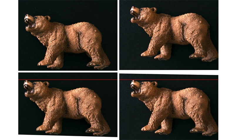
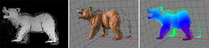
Wurden alle möglichen Zielumgebungen entlang der Epipolar-Geraden mit der Referenzumgebung verglichen, wird im Falle lokaler Stereo-Algorithmen in der Regel die Zielumgebung mit der höchsten Ähnlichkeit als finale Korrespondenz gewählt. Ist die Korrespondenzsuche abgeschlossen, so liegt bei einem rektifizierten Stereosystem für jeden Pixel in der Referenzansicht (sofern eine eindeutige Korrespondenz gefunden wurde) die Entfernungsinformationen in Form der Disparität vor, das heißt in Form des Versatzes in Pixeln entlang der entsprechenden Bildzeile. Die Rede ist hier auch von Disparitätsbild oder Disparitätskarte.
Mit Hilfe der zuvor kalibrierten Brennweite internen und externen Parameter lässt sich die Disparität wiederum in tatsächliche metrische Entfernungsinformationen umrechnen. Wird diese Entfernung für jeden Punkt berechnet, an dem eine Disparität geschätzt werden konnte, ergibt sich ein dreidimensionales Modell in Form einer sogenannten Punktwolke. Im Fall homogener oder stark repetitiver Szenen kann der Einsatz lokaler Stereoverfahren zu Fehlschätzungen führen, da mehrere Punkte mit gleichwertigen Ähnlichkeiten in der Zielansicht existieren können. Globale Stereo-Verfahren, die zusätzliche Bedingungen an die finalen Disparitätskarten stellen - zum Beispiel in Form möglichst ähnlicher benachbarter Tiefenwerte - können hier Abhilfe schaffen, sind aber auch deutlich rechenaufwendiger. Oft ist es hier einfacher, durch einen Projektor künstliche Strukturen auf das Objekt zu projizieren und so eine Eindeutigkeit der Korrespondenzen herbeizuführen ("Projected-Texture-Stereo"). Dabei ist der Projektor nicht bezüglich der Kameras zu kalibrieren, da er lediglich als künstliche Strukturquelle dient.
Beschleunigung durch GPUs
Gilt es, hohe Bildraten bei gleichzeitig hohen Ortsauflösungen zu gewährleisten, lässt sich die Berechnung der 3D-Informationen durch moderne GPUs erheblich beschleunigen. Bei der finalen Integration eines Stereosystems in bestehende Umgebungen setzt die Firma The Imaging Source beispielsweise auf modulare Lösungen: So kann für die Gewinnung der 3D-Informationen wahlweise das unternehmenseigene C++-SDK mit optionaler GPU Beschleunigung in Verbindung mit Kameras aus dem Portfolio von The Imaging Source oder aber HALCON von MVTec als Umgebung zum Einsatz kommen. Während das SDK es ermöglicht, mit geringem Aufwand Stereosysteme zu kalibrieren sowie 3D-Informationen zu akquirieren und zu betrachten, so bietet "Halcon" zusätzliche Möglichkeiten wie die Hand-Auge-Kalibrierung für die Integration in Robotersysteme oder weiterführende Algorithmik wie etwa die Registrierung von CAD-Modellen bezüglich der akquirierten 3D-Daten.
Der obige Artikel, verfasst von Dr. Oliver Fleischmann (Projektmanager bei The Imaging Source), wurde in der Mai-Ausgabe der Zeitschrift Computer&AUTOMATION unter dem Titel, "3D-Sehen leicht gemacht veröffentlicht." Unter folgenden Links finden Sie weitere Informationen zu unserem IC 3D Stereo Kamera-System und über das IC 3D SDK.