
Connecting Strobe and GP Out (Open Drain Outputs)
The strobe (flash) and GP Out connections on The Imaging Source cameras are Open Drain MOSFET. In simple terms, these outputs behave like a switch. This means that no voltage can be measured unless an external power source and resistor are connected.
To use the output, connect a pull-up resistor and a supply voltage of up to 24 V DC as shown below. Please note: The output current must not exceed 200 mA.
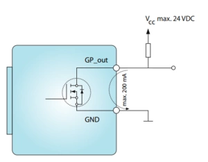 Pin assignments for older cameras can be found under "Camera Application Notes" on our Application Notes page.
For newer cameras (e.g., 33U,37U,38U, 33G,37G,38G series), please refer to the Technical Reference Manual available on the camera product page under the "Documentation" tab.
Another example circuit is shown below:
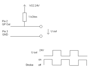 Please note that pin numbering may vary between camera models. The relationship between "Uout" and "Strobe" depends on the strobe polarity and the camera's "Line Invert" setting.
For further questions, please use our contact form